Splitting 240V Stove & Dryer Outlets to power lights
Hi,Problem with electricity....What is the real amps. of a stove tie-in (220 V) ??? If I have a stove tie-in for shotting ... What is the real amps available in each 110 V phase ???? By the way ,,,, what is the difference between stove tie-in and dryer tie-in
Thank you Gabriel Rochette
A stove or range plug is typically 50A per 120V leg of the single phase (two hot legs) 240V circuit. A dryer plug is typically 30A per 120V leg. You can safely and legally use these 240 volt wall outlets to power Quartz lights up to 5k and even HMIs as large as a 6k if you know how. Other common 240 volt wall outlets are air conditioner outlets, outlets for large copy machines in offices, and the outlets for motorized equipment and compressors in industrial plants. If you look at the breaker of these circuits on the building service panel you will notice that they use two pole breakers - either 30A or 50A. Each pole of the breaker is in a sense an independent 30A or 50A 120 volt circuit. That is, if you measure the voltage from each pole of the breaker to ground it will be 120 volts, and if you measure the voltage between the two poles of the breaker you will notice that it is 240 volts. The 120 volts of the two poles adds up to 240V because the 120V circuits are on opposing legs (and are therefore additive) of either a single phase electrical service of a house, or a single phase secondary step down transformer of an office or industrial plant. In residential settings, this is how higher voltages are supplied to household appliances like Dryers, Electric Ranges, Air Conditioners, and Heaters that require more power than can be reasonably supplied by a single 120V circuit. Many of these household and industrial 240V receptacles use a three wire system (no neutral) because they are designed to power single phase motors or heating elements that draw a perfectly balanced load and return no current because the single phase service legs are 180 degrees out of phase and cancel each other out.
The only safe way to pull power from 3-wire 240V circuits (hot, hot, ground, no neutral) is to run your lighting load through a 240v-to-120v step down transformer. A transformer converts the 240 volts supplied by these industrial and household 240V receptacles back to 120 volts in a single circuit that is the sum of the two legs of the circuit. For instance, a transformer can make a 60A/120v circuit out of a 30A/240v dryer circuit that is capable of powering bigger lights, like a 5k. What makes it safe to use a step town transformer is that the transformer automatically splits the load of whatever you plug into it evenly over the two legs of the 240V circuit. Where there is no high leg, the loads on each leg of the 240V circuit cancel out and there is no return that would require a separate neutral.
Some Gaffers will advocate the use of a "Splitter Box." You have to be really careful when splitting 240 volt circuits. If the 240 volt circuit is a four wire system (the receptacle has four slots: one for ground, one for neutral, and two for hot), one can use a distro box that splits the two hot circuits as long as it is wired so that each circuit has a ground and neutral. Where you run into trouble is when the 240V circuit uses a three wire system (the receptacle has three slots: one for ground, and two for hot, and no neutral.) Many older household and industrial 240V receptacles use a three wire system (no neutral) because they were wired for the sole purpose of powering single phase motors or heating elements that draw a perfectly balanced load and return no current. A perfectly balanced load doesn’t require a neutral because the single phase service legs are 180 degrees out of phase and cancel each other out – hence there is no return that would require a separate neutral (a later revision to the NEC required all 240V circuits to include a neutral.)
You run into trouble with this kind of circuit when you start to pull an unbalanced load on your "Splitter Box." And, where under most production situations you can never perfectly balance your lighting load, the two 120V circuits that make up this 240V circuit will not have 100% phase cancellation and the extra current of the high leg will not have a safe return path because by necessity with a three wire system you have had to bond the ground and the neutral in the splitter box (after all what else can you do with the ground and neutral of your splitter box but to bond them when plugging into a three wire 240V circuit.) There are some people that will argue that it is not such a big deal to carry current on the ground wire. I would argue that it is both unsafe and unwise to carry current on the ground wire. It is unsafe because the ground wire is intended only as a default conduit in the event of equipment failure (which is why it is permissible according to the National Electrical Code (NEC) to use a smaller conductor for the ground wire.) It is unwise because bonding ground and neutral after the service side of a main service head (which is what you have to do with the ground and neutral of a splitter box when plugging into a three wire 240V circuit.) is a violation of the NEC. To quote Mike Holt, of Mike Holt Enterprises, Inc. again: “The National Electrical Code (NEC) requires a neutral-to-ground connection to be made at service equipment only and there shall not be any neutral-to-ground connection on the load side of service equipment [250-23(a), 250-24(a)(5)]” (full excerpt is available online at his website) If some one were to fall off a ladder because they took a non-lethal shock because the cable they were handling was carrying current on the ground wire your liability insurance would be null and void because you were using equipment that need not meet code.
It is also unwise to carry current on the ground wire because it can induce ground loops. It is a given that whenever you carry current on the ground wire there will be a slight difference in the voltage between receptacles in the power distribution system. A ground loop occurs when there is more than one ground connection path between two pieces of equipment and there exists a voltage differential. Under these circumstances, the duplicate ground paths form the equivalent of a loop antenna that very efficiently picks up interference currents. Lead resistance transforms these currents into voltage fluctuations. As a consequence of ground loop induced voltages, the ground reference in the system is no longer a stable potential (a floating ground), so signals ride on the noise. The noise becomes part of the program signal. The result is that the unwanted signal will be amplified until it is audible and clearly undesirable. Whenever you have current on the grounding system as well as the multiple connections between electronic components that is typical of HD production packages, there is the potential for a "ground loop."
Interference bars caused by current induced on a ground loop by high THD.
Small voltage differences just cause noise to be added to the signals. This can cause an audio hum, interference bars to video signals (above), and transmission errors in computer networks. Higher currents can cause more serious problems that can damage equipment like sparking in connections and burned wiring. As more and more electronic components, like lap top computers, hard drives, and HD monitors, are integrated into the typical location HD production package, ground loops become more of a hazard.
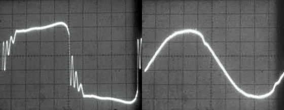
Left: Conventional generator power w/ THD over 100 percent caused by pkg. of non-PFC Elec. HMI & Kino Ballasts. Right: Same lighting Pkg. but with PFC HMI & Kino Ballasts powered by our modified Honda EU6500is inverter generator. Note the THD is now under 7 percent.
It is also worth noting that “ground loops” can result from the harmonic currents that non-power factor corrected electronic ballasts (HMI & Kino) throw back into the distribution system. Current on neutral conductors with a high Total Harmonic Distortion (THD) value will induce voltage in ground wires greater than the 2 volt maximum stipulated by IEEE Standard 1100-1992 "Recommended Practice for Powering and Grounding Sensitive Electronic Equipment." For instance, there was an episode, recently reported on CML, of a pilot shooting in HD that found they had 50 volts between the shield of the SDI line and ground. In that case the problem was fixed by running a "Drain" wire from the SDI Shield back to the Genny via the electrical lunchbox at the DIT station. For more details on why this is I suggest you read my newsletter article on the use of portable generators in motion picture production. The article is available on our
website.
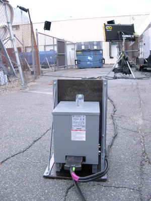
A PFC 2.5 & 1.2 HMI Pars, PFC 800w Joker HMI, Kino Flo Flat Head 80, 2 ParaBeam 400s, and a ParaBeam 200 powered by a modified Honda EU6500is through a 60A Full Power Transformer/Distro
The only safe way to pull power from a three wire 240V wall outlet that meets the requirements of the National Electrical Code, and won't create ground loops, is to run your lighting load through a 240v-to-120v step down transformer. And unlike a 240V "Splitter Box" where you have to meticulously balance your load, a transformer greatly simplifies your set electrics by automatically splitting the load. As long as you plug lights in through the transformer, you no longer have to carefully balance the load over the two 120V circuit/legs because the transformer does it for you automatically. If you outfit the transformer with a 60 Bates receptacle, you can use 60A GPC extension cables, 60-to-60 Splitters, and fused 60A GPC-to-Edison Breakouts (snack boxes) to run power around set - breaking out to 20A Edison outlets at convenient points (rather than one central point.) The best part about using a transformer with a 240V receptacle in this fashion is that no matter where in the distribution system you plug in, the transformer automatically balances the additional load, so that you don't have to.
The PFC 2.5 & 1.2 HMI Pars, PFC 800w Joker HMI, Kino Flo Flat Head 80, 2 ParaBeam 400s, and a ParaBeam 200 of our HD P&P Pkg. powered by our modified Honda EU6500is through our 60A Full Power Transformer/Distro
I use transformers to power bigger HMIs (2.5-4Kw) in situations where a tie-in is not an option and the budget doesn’t permit for a tow generator. Where the production budget is particularly tight, I use a package consisting of two transformers and a portable generator. I use one transformer to access more power through a 240V circuit on location to run lights inside; while the other I use our our modified Honda EU6500is generator to bring larger HMIs in the windows from outside. This approach eliminates the need for a dangerous tie-in or expensive tow generators, it also greatly reduces the amount of cable that has to be run.
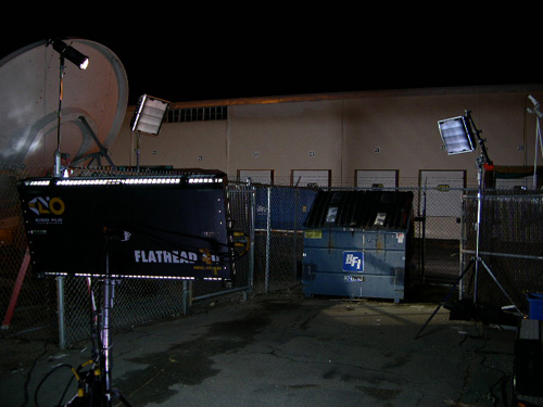
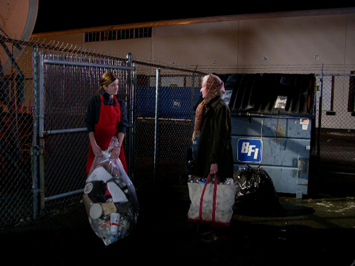
Wide Shot of Night exterior scene lit with our HD P&P Pkg.
For those who would like to see samples of what can be accomplished with this basic package, I have attached these links to production stills of the PBS and History Channel historical documentaries shot entirely, or in part, with just a couple of transformers and a Honda generator.
The History Channel’s “Unsolved History” episode
“Presidential Assassins”
American Experienes Typhoid Mary Biography
"The Most Dangerous Women in America"
WGBH’s Ben Franklin Biography
“Franklin”
Or, use this link for more details about
using step-down transformers on set: . By giving you access to more house power through common 240V house outlets, a transformer can quite often eliminate the need for tie-ins or generators.
- Guy Holt, Gaffer, ScreenLight & Grip, Boston